VACOMASS® simulation
- CFD-flow simulation in the measuring piping section
- under consideration of piping geometry and details as well as further installations like elbows, T-pieces, and control valves at the inlet and outlet of the flowmeter
- Calculation of the required length of piping sections
- Calculation of the pressure drop
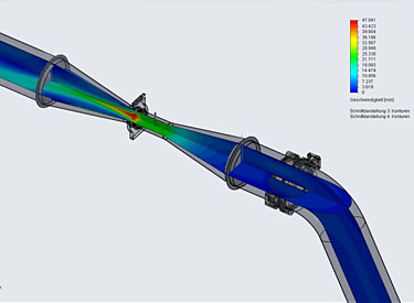
VACOMASS® simulation presents the results of a 3D-CFD (Computational Fluid Dynamics) simulation of the flow in the piping section. The detailed piping section, consisting of different parts like elbows, T-pieces, reduction, and expansion but also a control valve and flow meter sensor, is designed mechanically using a 3D construction tool.
The complete geometry is read into a CFD-software and the defined body volume is divided into many small volumes (grid generation). Then border and initial conditions (like gas type, gas flow, pressure, temperature, and others at the inlet and geometrical borders of the body) must be defined, the turbulence model needs to be selected and the iterative calculation can be started.
The flow in the piping section will be computed. Possible turbulences and flow stalls, which produce an unnecessary pressure drop and which must be paid later constantly by the operator, become visible and can be reduced or even avoided by an adaptation of the geometry of the piping section (e.g. increase of the length of the expansion piece), taking local situation into consideration.
Furthermore, the computation can be done at different opening degrees of the control valve whether the simultaneous flow profile correction of the flow signal must be used or not.
Last but not least the pressure drop of the control valve as well as the pressure drop of the whole piping section can be calculated. So it can be examined if the recommendation of the German Association of Water and Wastewater (ATV-DWA) can be fulfilled or not.
Related products

Explosion-proof Tank Inspection Vessel Light – BAK85
Explosion protection to CENELEC IEC NEC Can be used in Zone 1 and Zone 2 Zone 21 and Zone 22 Class I, Zone 1 and Zone 2 Class I, Division 2, Group A, B, C, D
View more
Explosion-proof Medium Intensity Aircraft Warning Light – BSZD85-C
Explosion protection to CENELEC IEC NEC Can be used in Zone 1 and Zone 2 Zone 21 and Zone 22 Class I, Zone 1 and Zone 2 Class I, Division 2, Group A, B, C, D
View more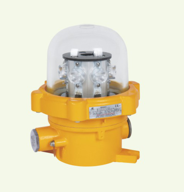
Explosion-proof Low Intensity Aircraft Warning Light – BSZD85-E
Explosion protection to CENELEC IEC NEC Can be used in Zone 1 and Zone 2 Zone 21 and Zone 22 Class I, Zone 1 and Zone 2 Class I, Division 2, Group A, B, C, D
View more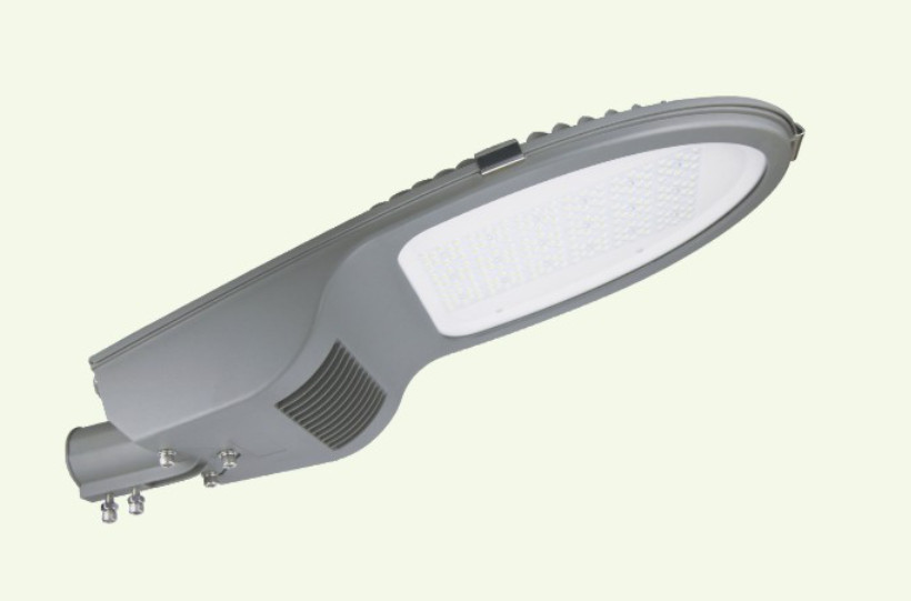
Explosion-proof Street Lamp – BAM52
Explosion protection to CENELEC IEC NEC Can be used in Zone 1 and Zone 2 Zone 21 and Zone 22 Class I, Zone 1 and Zone 2 Class I, Division 2, Group A, B, C, D
View more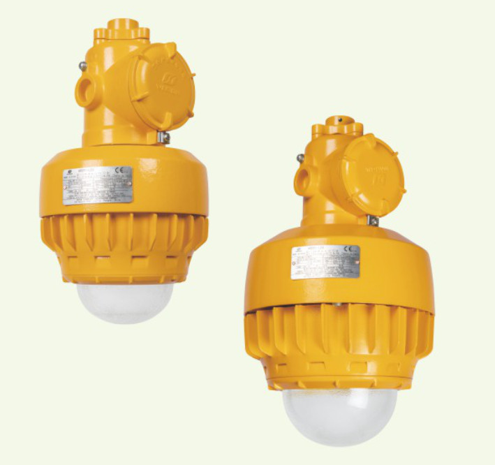
Explosion-proof Light Fitting – HRY91-LED
Explosion protection to CENELEC IEC NEC Can be used in Zone 1 and Zone 2 Zone 21 and Zone 22 Class I, Zone 1 and Zone 2 Class I, Division 2, Group A, B, C, D
View more